Containerized SWRO System Installation: Site Preparation and Commissioning Checklist
Temmuz 26, 2026
How to Determine SWRO Membrane CIP Timing: Pressure, Flow and Salt Rejection Guide
Ağustos 17, 2026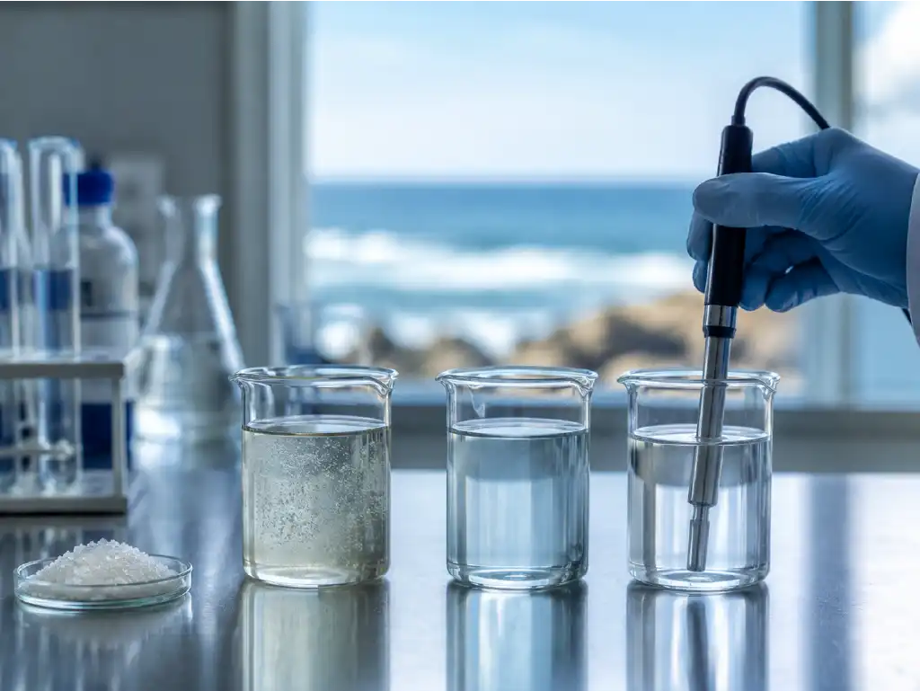
An increase in product water conductivity at a seawater reverse osmosis plant suggests that more dissolved ions are passing into the permeate. However, an initially high reading does not necessarily mean that the membranes have deteriorated. An SWRO conductivity increase may be caused by sensor contamination, incorrect temperature compensation, improper sampling, changes in operating conditions, sealing problems or actual membrane damage. Therefore, the correct approach is to verify the measurement and systematically isolate the variables before replacing any component.
Instead of relying on a single instantaneous value, feedwater, concentrate and permeate data should be evaluated together. A definitive diagnosis cannot be made using conductivity alone without reviewing flow, pressure, temperature, recovery rate and historical performance records. In projects where water quality targets are critical, such as drinking water, process water or hotel applications, field measurements should be confirmed using a calibrated reference instrument and supported by laboratory analysis when necessary.
Reinmeer Water Treatment Systems follows a project-specific approach that treats changes in SWRO product water conductivity as more than a simple alarm. The objective is to identify the cause of the SWRO conductivity increase and determine which factor is affecting the system’s salt rejection performance. The following inspection sequence helps examine potential sources, from the sensor to the membrane, in a safe and measurable way.
How Can a Conductivity Increase Be Confirmed?
The first question in a reliable diagnosis should be: “Has the value actually increased?” An SWRO conductivity increase should be verified at the same sampling point, at the same reference temperature and under comparable operating conditions. Measurements obtained under different conditions cannot be compared directly. Remineralization, chemical dosing or backflow from a storage tank may also raise the conductivity downstream of the membrane outlet. The sampling location, measurement time and operating status of the system must therefore be recorded.
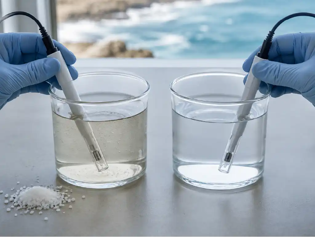
How should feedwater and product water conductivity be compared?
The first step is to measure feedwater conductivity and membrane permeate conductivity as close to simultaneously as possible. The permeate sample should be collected from a reliable point close to the membrane product header, before post-treatment or remineralization. Changes in coastal conditions, tides, rainfall or seawater intrusion into a feed well can raise feedwater conductivity. In such cases, permeate conductivity may increase even when the membrane continues to reject salt at the same rate.
Although salt rejection is assessed using ion concentrations under laboratory conditions, temperature-corrected conductivity values can be used as a practical field indicator. The approximate calculation is: salt rejection rate (%) = [1 − (product water conductivity / feedwater conductivity)] × 100. For example, if the feedwater conductivity is 50,000 µS/cm and the product water conductivity is 500 µS/cm, the approximate rejection rate is 99%. This calculation is meaningful only when both readings have been converted to the same reference temperature and measured within the correct instrument range.
When investigating an SWRO conductivity increase, the absolute permeate value should not be considered alone. Calculated salt passage and historical trends should also be monitored. A consistent rise in permeate conductivity while feedwater conductivity remains stable provides a stronger indication of declining separation performance. If both values increase together, changes in raw water quality may be playing a significant role.
- Samples should be collected only after the system reaches stable operating conditions.
- Feedwater, concentrate and permeate samples should be collected in separate, clean containers.
- The online sensor reading should be compared with a calibrated portable instrument.
- Pressure, flow, temperature and recovery rate should be recorded using the same timestamp.
- Measurements taken after remineralization or disinfection should not be used as direct indicators of membrane performance.
The ability of modern SWRO membranes to produce low-salinity product water from seawater through high salt rejection is also described in a seawater reverse osmosis study published by the U.S. Bureau of Reclamation. Nevertheless, the target value must be determined on a project-specific basis according to feedwater composition, membrane model, temperature, pressure, recovery rate and intended water use.
How should temperature compensation and sensor calibration be checked?
Conductivity is temperature-dependent. As water temperature rises, ion mobility increases and the uncompensated conductivity reading generally rises as well. Instruments therefore commonly convert the measured value to a 25°C reference. However, an incorrect temperature coefficient, a faulty temperature element or disabled automatic compensation may create the appearance of an SWRO conductivity increase even when the actual water quality has not changed. A USGS study on conductivity temperature compensation highlights that standard correction methods may not provide the same accuracy for every water composition.
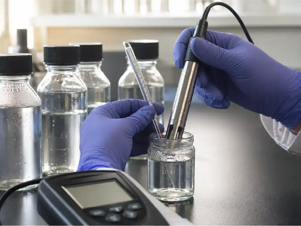
Before removing the online sensor, its reading should be compared with a recently calibrated and traceable reference instrument using the same sample. The temperature reading should then be verified with an independent thermometer. If a significant difference is detected, the probe surface should be inspected for biofilm, mineral deposits and trapped air bubbles. Insufficient sample flow, cable damage, poor grounding and an incorrect cell constant should also be investigated.
The calibration solution must be suitable for the sensor’s operating range, within its expiry date and free from contamination. The probe should be rinsed gently with purified water without leaving a residual water film that could dilute the sample. Used calibration solution should never be returned to its original container, and sufficient time should be allowed for the sensor to reach a stable reading. Verifying the calibration with a second standard provides evidence that the adjustment was successful.
If the reading returns to normal after the sensor is cleaned or replaced, the problem may not be related to the membrane. If both the online sensor and reference instrument show a high value, the SWRO conductivity increase should be considered genuine, and the investigation should proceed to hydraulic, mechanical and chemical causes.
| Observed Condition | Possible Source | Initial Check |
|---|---|---|
| Reading fluctuates in the same direction as temperature | Temperature compensation or temperature sensor | 25°C reference setting and independent thermometer |
| Online sensor reads high while portable meter reads normally | Dirty, faulty or incorrectly calibrated probe | Cleaning, standard solution and cell constant |
| Sudden increase across all trains | Feedwater change, common header or shared sensor | Raw water analysis and line valves |
| Sudden increase in one pressure vessel | Seal, adapter or mechanical damage | Vessel-specific permeate profiling |
| Gradual increase accompanied by performance loss | Fouling, scaling or membrane ageing | Normalized trends and differential pressure |
Possible Causes of Increased Conductivity
Once the measurement has been verified, the pattern of the SWRO conductivity increase should be examined. Did the change occur suddenly or gradually? Is it limited to one train or present throughout the system? Did it begin after cleaning, chemical dosing or system start-up? Answering these questions prevents unnecessary membrane replacement and narrows the correct intervention area for a seawater RO failure.
Membrane oxidation, seal leakage and mechanical damage
Polyamide SWRO membranes are sensitive to free chlorine and other strong oxidizing agents. If dechlorination is insufficient after disinfection, the dosing pump deviates from its setpoint or oxidation-reduction potential control is inadequate, the membrane’s active layer may be damaged. Oxidation commonly increases salt passage, which is observed as an SWRO conductivity increase, and may cause irreversible performance loss. When oxidation is suspected, free chlorine, ORP, sodium bisulfite dosing and historical alarm records should be reviewed together.
Conductivity is not the only indicator of chemical damage. Normalized permeate flow, salt passage, pH and cleaning history should also be evaluated. Clean-in-place procedures performed at an unsuitable pH or temperature, incorrect chemical concentrations and insufficient rinsing may affect the membrane structure. Applying aggressive cleaning without reviewing the membrane manufacturer’s operating limits can make the problem worse.
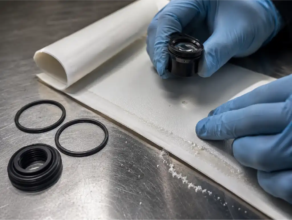
In the event of seal leakage, saline feedwater or concentrate can enter the permeate line without passing through the membrane’s active layer. Interconnector O-rings, end adapters, permeate tube connections and brine seals may be pinched or cut during installation or lose elasticity over time. When this occurs, an SWRO conductivity increase usually begins suddenly and becomes more pronounced in a specific pressure vessel.
Mechanical damage may result from pressure surges, improper start-up, reverse flow, excessive permeate backpressure, membrane element telescoping or incorrect alignment inside the pressure vessel. A crack in the permeate tube or a tear in the membrane surface may also create a shortcut for saline water. Vessel-specific permeate sampling, probing and membrane autopsy, when required, can be used to locate the damage.
As explained on Reinmeer’s seawater reverse osmosis systems page, membrane selection, pretreatment, high-pressure operation and post-treatment must be considered as one integrated process. Focusing only on the membranes can cause problems in common headers, seals or downstream piping to be overlooked.
High recovery, pressure problems and concentrate mixing
The recovery rate indicates how much of the feedwater is converted into product water. Operating above the design recovery increases salinity and osmotic pressure on the concentrate side. Concentration polarization at the membrane surface becomes stronger, creating a higher risk of salt passage, SWRO conductivity increase and scaling. Excessively closing the concentrate valve to raise product flow may appear to increase capacity temporarily, but it presents a risk to SWRO product water conductivity and membrane life.
Insufficient feed pressure may also affect separation performance by reducing the net driving pressure and causing an SWRO conductivity increase. Pump wear, clogged filters, poor suction conditions, incorrect frequency settings or an imbalance in the energy recovery device should be investigated. Simply increasing pressure is not an appropriate solution. Permitted pressure, flow and recovery limits must be maintained together.
High backpressure in the permeate line may create an undesirable mechanical load on the membrane. The risk of reverse pressure is particularly important during shutdown and start-up when the correct valve sequence is not followed. It is therefore necessary to determine whether the alarm occurs during normal operation or immediately after the system is started.
Concentrate and product water may also mix outside the membrane vessels. An incorrectly positioned valve, leaking check valve, line connected to a common storage tank, cracked header or incorrect CIP connection can increase conductivity. If the sample at the membrane outlet is normal while the value in the product tank is high, the investigation should be redirected to post-treatment, piping and storage.
If an SWRO conductivity increase occurs together with rising differential pressure, the likelihood of fouling or scaling becomes stronger. If differential pressure remains normal while salt passage increases suddenly, the sensor, seals, headers or chemical damage should receive greater attention. Nevertheless, a definitive conclusion should be based on normalized performance data and field analysis.
Systematic Inspection Sequence for an SWRO Conductivity Increase
Troubleshooting an SWRO conductivity increase should begin with the point that is easiest to verify and requires the least intervention. Before opening pressurized equipment, the facility’s lockout, depressurization and occupational safety procedures must be implemented. The recommended inspection sequence is as follows:
- Record the alarm time, historical trends and operating status at the moment of the alarm.
- Verify the online reading with a calibrated portable instrument at the correct sampling point.
- Check temperature compensation, probe cleanliness, cell constant, sample flow and electrical connections.
- Measure feedwater, permeate and concentrate conductivity simultaneously and calculate the salt rejection rate.
- Compare normalized permeate flow, salt passage, pressure, differential pressure and recovery trends with the original design data.
- Review chemical dosing, free chlorine, ORP, CIP and start-up records.
- Prepare train, pressure-vessel and, when required, element-specific permeate profiles.
- Inspect seals, adapters, headers and valves before planning a detailed membrane examination.
Expert note: Do not use raw conductivity alone as an acceptance criterion or as the basis for a membrane replacement decision. Performance data must be normalized when temperature, feed salinity, pressure or recovery changes. Verifying the sensor before taking invasive action reduces downtime and prevents unnecessary component costs.
Maintaining comprehensive automation records allows small deviations, including an SWRO conductivity increase, to be identified before they reach the alarm threshold. Reinmeer’s technology and safety approach provides additional information about the coordinated operation of pressure and flow sensors, conductivity measurement and alarm logic. The maintenance plan should clearly define calibration frequency, sampling points, acceptable ranges and the chain of responsibility to follow when a deviation occurs.
Final Evaluation for Protecting SWRO Product Water Quality
An SWRO conductivity increase is a performance problem that cannot be attributed to a single component without proper verification. Once measurement error has been eliminated, changes in feedwater, temperature, recovery, pressure, chemical exposure, mechanical integrity and cross-contamination between lines should be evaluated using the same dataset. The most reliable diagnosis is obtained by comparing current normalized data with the system’s original design and acceptance-test values.
Periodic sensor calibration, regular water analysis, effective pretreatment, controlled start-up and CIP procedures that comply with manufacturer limits help reduce conductivity deviations. Early intervention during a gradual decline supports membrane protection, stable product water quality and controlled energy consumption.
Frequently Asked Questions
What should SWRO product water conductivity be?
There is no single universal value. The target depends on feedwater salinity, temperature, membrane model, system stage, intended-use standard and remineralization design. The most reliable assessment compares the current measurement with the acceptance-test value and the membrane manufacturer’s normalized performance projection.
Should membranes be replaced immediately when conductivity increases?
No. The sampling point, sensor calibration, temperature compensation and feedwater changes should be verified first. Salt rejection, pressure, flow and recovery should then be examined. If the actual cause is a seal leak or common-line mixing, replacing undamaged membranes will not solve the problem.
What is the relationship between salt rejection rate and conductivity?
When feedwater and permeate conductivity are measured at the same reference temperature, their ratio can provide an approximate field indicator of salt rejection. As permeate conductivity increases relative to feedwater conductivity, the calculated rejection rate decreases. Ion analysis and project-specific quality criteria should also be considered during final verification.
Why can product water conductivity remain high after CIP?
Chemical residues may remain because of insufficient rinsing, or the system may not yet have reached stable operating conditions. Incorrect cleaning chemicals, concentrations, pH or temperature may also have damaged the membrane. Rinse-water quality, pH, conductivity trends and CIP records should be reviewed together.
Why does conductivity fluctuate even when the sensor is functioning normally?
Feedwater salinity and temperature, flow, pressure, recovery, remineralization dosing or storage-tank backflow may be changing. Air bubbles and irregular sample flow can also create unstable readings. The timing of the fluctuation should be compared with other process trends.
Can a seawater RO failure be diagnosed remotely?
Trend records, alarm history, water analysis and operating parameters can be reviewed remotely for an initial assessment. However, fieldwork is necessary when sensor verification, sampling, sealing checks or mechanical inspection are required. Remote analysis can accelerate the preparation of an accurate on-site inspection plan.
Protect Your SWRO Performance with Reinmeer
If deviations in product water quality are affecting your production, hospitality or marine operations, simply resetting the alarm will not provide a permanent solution. Reinmeer Water Treatment Systems evaluates water analysis, operating trends, sensor accuracy, membrane performance and hydraulic conditions on a project-specific basis to help identify the actual source of the problem. A technical investigation of an SWRO conductivity increase can prevent unnecessary membrane replacement, establish the correct maintenance sequence and restore the target water quality safely.
For performance evaluation, periodic inspection, maintenance planning or information about a new seawater treatment project, you can contact the Reinmeer engineering team. The technical team can compare current measurements with the design data and provide a clear assessment of intervention priorities and practical service steps. Site conditions, capacity requirements, raw water characteristics and intended use are evaluated together to develop a technically and economically suitable solution.