SWRO Conductivity Increase: Why Does Product Water Conductivity Rise? Membrane and Sensor Inspection Guide
Ağustos 9, 2026
How to Select an SWRO Intake Structure: Open-Ocean Intake vs. Beach Wells
Ağustos 28, 2026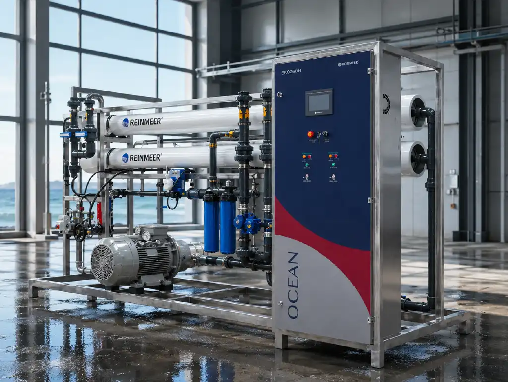
In seawater reverse osmosis plants, the cleaning decision should be based on persistent changes in normalized operating data rather than a fixed calendar. Performing SWRO membrane CIP too early increases chemical consumption, downtime and the number of times the membrane is exposed to cleaning chemicals. Delaying it can compact the fouling layer, raise energy demand and lead to performance loss that may not be fully reversible. A reliable decision requires the combined evaluation of permeate flow, feed pressure, stage-specific differential pressure, permeate conductivity, temperature, feed salinity and recovery.
CIP stands for “cleaning in place” and describes controlled chemical cleaning performed without removing membrane elements from their pressure vessels. However, every decrease in raw permeate flow does not indicate membrane fouling. Lower seawater temperature, higher feed salinity, pump performance, valve position, sensor drift or a change in recovery can produce similar symptoms. A reliable SWRO membrane CIP program must therefore be based on a clean-membrane baseline, consistent operating records, correct data normalization and technical analysis of the likely foulant.
How Can You Tell When SWRO Membrane CIP Is Required?
The need for cleaning should be evaluated as a trend rather than from one instantaneous reading. After new membranes are commissioned or successfully cleaned, reference data should be recorded under stable conditions. The baseline should include temperature, conductivity, stage pressures, differential pressure, feed, permeate and concentrate flows, pH and recovery. Normalizing comparable daily records helps distinguish seasonal effects from actual performance loss.
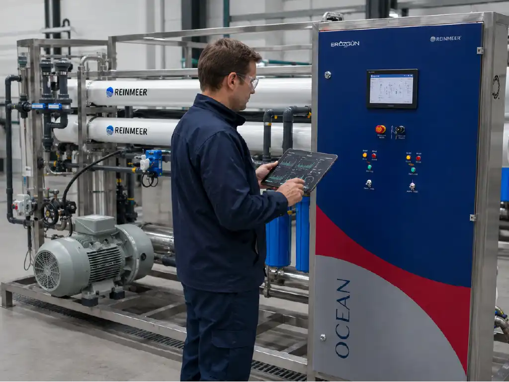
Common SWRO membrane CIP warning points include an approximately 10% decline in normalized permeate flow, a 15% increase in normalized differential pressure or a 10% increase in normalized salt passage. These are not universal limits. Manufacturer guidance, design recovery, feedwater analysis and previous cleaning results take priority. The decision is stronger when several verified indicators move together under stable operating conditions.
Decline in Normalized Permeate Flow
Permeate flow is one of the primary indicators of a membrane’s ability to pass water. Raw flow, however, changes significantly with temperature. Colder seawater has higher viscosity, so even a clean membrane can produce less permeate. Feed pressure, osmotic pressure, recovery and membrane age also affect output. Comparing only the flowmeter reading with the previous month can therefore lead to an incorrect SWRO membrane CIP decision.
Normalization converts measurements from different operating conditions to a shared reference. The calculation should follow manufacturer software or an approved plant procedure so the SWRO membrane CIP decision reflects actual membrane behavior. A confirmed flow loss of roughly 10% should trigger a fouling investigation. First-stage decline may suggest colloidal loading or biofouling, while final-stage decline may indicate mineral scaling. These patterns guide investigation but do not replace sampling.
When flow decreases while feed pressure rises, more energy is required to maintain production. If flow falls while pressure and permeate quality remain unchanged, operators should check flowmeter calibration, pump speed, valve positions, cartridge-filter loss and temperature compensation. Data verification and hydraulic checks should come before seawater RO membrane cleaning.
Changes in Differential Pressure and Salt Rejection
Differential pressure is the pressure loss across a membrane stage. As particles, biofilm or scale accumulate in the feed channel, flow resistance rises. A normalized increase of approximately 15%, particularly with lower permeate flow, is a strong SWRO membrane CIP indicator. Stage-specific monitoring is more useful than total system pressure loss because it shows where fouling is concentrated.
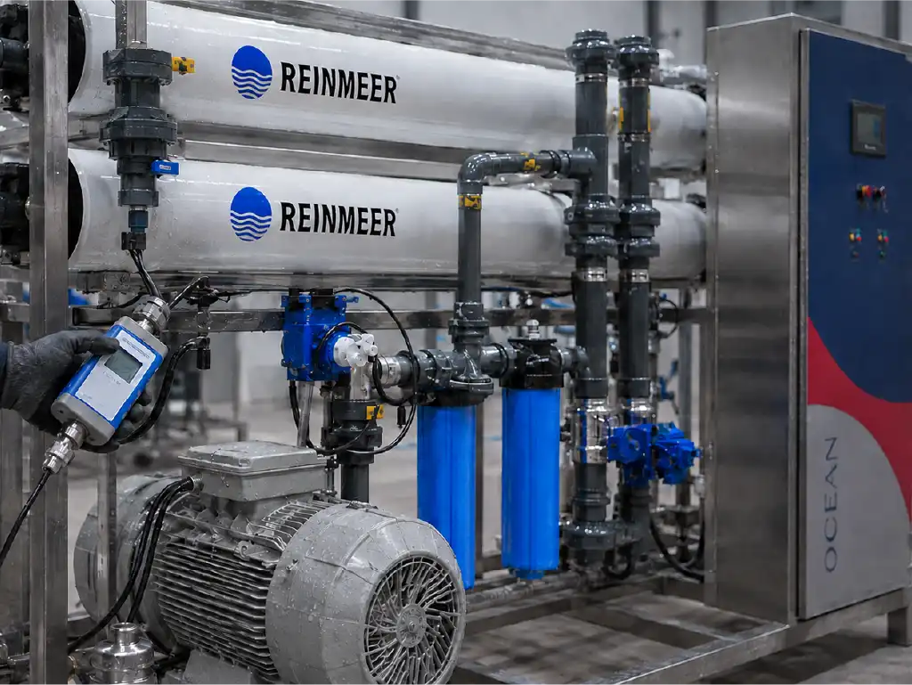
Salt rejection is calculated using feed and permeate conductivity or TDS values. When salt passage increases, permeate conductivity rises and product-water quality deteriorates. This change is not always caused by membrane fouling. A damaged O-ring, incorrectly connected interconnector, membrane telescoping, oxidant exposure, excessive temperature, unsuitable pH or instrument error can also cause salt leakage. Mechanical integrity and instrumentation must therefore be inspected instead of assuming that chemical cleaning will correct every conductivity increase.
| Monitored Indicator | Common Warning Level | Possible Interpretation | First Check |
|---|---|---|---|
| Normalized permeate flow | Approximately 10% decrease | Organic, biological or mineral deposition | Temperature, pressure, salinity and flowmeter |
| Normalized differential pressure | Approximately 15% increase | Feed-channel blockage, biofilm or particles | Stage pressure sensors and pretreatment |
| Normalized salt passage | Approximately 10% increase | Fouling, seal leakage or membrane damage | Conductivity meter, O-rings and oxidant records |
| Feed pressure | Persistent increase at equal production | Permeability loss or hydraulic restriction | Pump, valves, cartridge filters and recovery |
The U.S. Bureau of Reclamation membrane process optimization report describes how differential pressure, normalized permeate flow and salt-passage trends can help predict time to cleaning. This is more informative than one SWRO membrane CIP alarm because it reveals the rate of deterioration. Site setpoints must still follow manufacturer limits and the approved operating procedure.
Expert Note: A cleaning decision should never be based only on the observation that “flow has decreased.” Temperature, feed salinity, recovery, chemical-dosing records, SDI or turbidity, cartridge-filter pressure loss and calibration status from the same operating period should be reviewed together. Performing chemical cleaning because of an incorrectly diagnosed sensor drift creates unnecessary downtime and can conceal the actual problem.
How Should the SWRO Membrane CIP Process Be Validated?
A successful SWRO membrane CIP is more than chemical circulation. Diagnosis, recipe selection, controlled temperature and flow, contact time, rinsing and normalized post-cleaning comparison form one process. Before cleaning, the train should be isolated, depressurized and, where applicable, flushed with RO permeate. The CIP tank, pump, filter, hoses and connections should also be checked for cleanliness.
Cleaning flow should provide adequate crossflow while remaining below the pressure that produces permeate. Returning the first heavily contaminated liquid to the tank can redeposit released foulants, so the approved procedure may direct it to drain. During recirculation, pH, temperature, color, turbidity and conductivity should be monitored to confirm that the solution remains effective.
Chemical and pH Selection According to Fouling Type
The SWRO chemical cleaning recipe must match the deposit chemistry before SWRO membrane CIP begins. Approved acidic cleaners may address calcium carbonate and certain metal oxides, while alkaline products are often used for organics, oils and biofilm. Silica, sulfate scale or mixed fouling may require chelants, surfactants or sequential cleaning. Selection should be supported by water analysis, antiscalant history, pretreatment records and, where possible, foulant analysis.
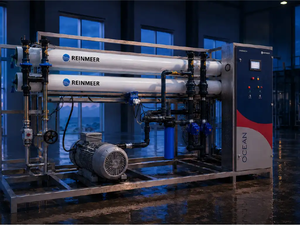
pH and temperature affect cleaning speed, but membrane resistance limits must not be exceeded. The allowable pH range may narrow as temperature rises. The safety data sheet, manufacturer bulletin and material-compatibility list should be reviewed together. Excessive concentration, temperature or contact time can damage the polyamide layer, seals, adhesives and piping.
Cleaning order matters when foulants are mixed. A mineral layer may cover biofilm, while an unsuitable acid step can compact organic deposits. The sequence should follow site analysis and manufacturer guidance. Acidic and alkaline solutions must not be mixed, and thorough rinsing is required between stages. Oxidizing biocides should not be used on polyamide membranes without explicit approval.
A typical procedure includes low-flow recirculation, controlled soaking and a second pass at higher crossflow. Temperature, pH and tank level must remain within the approved range. Rapid pH neutralization may indicate chemical consumption by the foulant. Chemical name, batch, concentration, preparation water, duration, flow, pressure, temperature and observations should be recorded.
Rinsing, Performance Testing and Return to Service
After SWRO membrane CIP contact is completed, membranes should be rinsed with RO permeate or manufacturer-approved water. Rinsing continues until return pH and conductivity reach acceptance limits and foam, color or residue disappear. Cleaning chemicals must not enter the product tank. Spent solution must be neutralized and disposed of according to environmental, safety and plant requirements.
Restarting should begin at low pressure and controlled flow. After removing air and checking for leakage or abnormal noise, pressure is increased gradually. Initial permeate goes to drain until quality criteria are met. Once stable, flows, stage pressures, conductivity, pH and temperature are recorded, normalized and compared with pre-cleaning values and the clean baseline.
Higher permeate flow alone does not validate cleaning. Differential pressure should fall, salt rejection should remain acceptable, feed pressure should decrease and performance should remain stable. If flow recovers while conductivity rises, investigate membrane damage or connection leakage. Unchanged differential pressure may indicate inadequate crossflow, the wrong chemical, low temperature, short contact or irreversible blockage.
If SWRO membrane CIP does not restore performance, the same recipe should not be repeated automatically. Review cleaning records, discharged solution, stage data, pressure-vessel connections and pretreatment results. An element may require inspection, autopsy or laboratory analysis. Persistent salt-passage increase can indicate oxidation or mechanical damage that chemical cleaning cannot repair.
How to Reduce SWRO Membrane CIP Frequency
Effective pretreatment is as important as correct SWRO membrane CIP. Seasonal algae, suspended solids, hydrocarbons and microbiological activity should be monitored. Filter backwashing, cartridge consumption, SDI, turbidity, antiscalant dosing and dechlorination require regular checks. The SWRO pretreatment selection guide explains how incoming load affects cleaning frequency, membrane life and stability.
Automation data should be monitored as normalized trends and rates of change, not merely archived. Properly configured Reinmeer sensors, PLC controls and remote monitoring can reveal pressure, flow and conductivity changes early. The Reinmeer technology and safety infrastructure presents automatic cleaning, real-time monitoring and project-specific control options.
Consistent operator records are equally important. Measurements should use comparable production modes and recovery, while calibration and maintenance changes are documented. This reduces false SWRO membrane CIP alarms. Shorter cleaning intervals require investigation of the intake, coagulation, filter loading, biocide strategy, antiscalant selection and piping dead zones.
Frequently Asked Questions
How Often Should SWRO Membranes Be Cleaned?
A fixed monthly interval is not appropriate. SWRO membrane CIP should be scheduled according to normalized flow, differential pressure and salt-passage trends. A plant with well-managed feedwater may operate for longer periods between cleanings, while seasonal biological loading or weak pretreatment can shorten the interval. Manufacturer criteria and the plant baseline must guide the decision.
Why Is Normalized Permeate Flow Used?
Raw permeate flow is affected by temperature, salinity, pressure and recovery. Normalization reduces the influence of these variables and helps reveal actual permeability loss. This prevents a natural flow decrease caused by colder seawater from triggering an unnecessary cleaning alarm.
Should CIP Begin Immediately When Differential Pressure Increases?
Sensor accuracy, flow, valve positions, cartridge filters and stage-specific data should be checked first. A persistent increase of approximately 15% in normalized differential pressure, when confirmed against manufacturer criteria and combined with other performance changes, is a strong indication that cleaning should be planned.
What If Salt Rejection Does Not Recover After CIP?
The conductivity sensor and sample analysis should be verified, followed by inspection of O-rings, interconnectors and membrane installation. Element autopsy may be required if oxidation or mechanical damage is suspected. Repeating the same cleaning recipe will not repair a damaged membrane and may create additional risk.
Can Municipal Water Be Used for CIP?
Preparation and rinse water must satisfy the membrane manufacturer’s quality requirements. Water containing hardness, metals, suspended solids or free chlorine can create new deposits or oxidation during cleaning. RO permeate is commonly preferred, but the available water should be analyzed before a site-specific decision is made.
Which Records Are Critical During SWRO Chemical Cleaning?
The chemical name and concentration, preparation-water quality, pH, temperature, flow, pressure, recirculation and soaking times, appearance of the return solution and normalized performance before and after cleaning should be documented. These records improve troubleshooting and make the next cleaning procedure more accurate.
Data-Driven Membrane Maintenance with Reinmeer
Correctly interpreting a decline in membrane performance requires more than selecting a cleaning chemical. Reinmeer water treatment systems evaluate raw-water characterization, pretreatment condition, sensor and automation data, chemical compatibility, cleaning procedures and recommissioning performance within one engineering framework. If your existing plant experiences frequent cleaning, increasing energy consumption, unstable pressure or declining product-water quality, you can request a project-specific assessment from an expert team. For new SWRO investments, system design can also be developed according to capacity, seawater analysis, intended use and site conditions. To protect membrane life, reduce unplanned downtime and maintain reliable water production through correctly timed SWRO membrane CIP, explore Reinmeer seawater desalination solutions and contact the team for technical information, site evaluation or a project quotation.
Images are for illustrative purposes and were generated using artificial intelligence.